Recording the WWVB Phase Modulation Test
March 10, 2012
ref: www.nist.gov/pml/div688/grp40/wwvb.cfm
(web archive)
ref: [time-nuts] WWVB phase modulation format?
ref: [time-nuts] WWVB NIST's WWVB phase modulation format paper from PTTI 2011
ref: [time-nuts] WWVB BPSK Receiver Project?
ref: [time-nuts] WWVB BPSK Receiver Project? (fwd)
ref: [time-nuts] WWVB phase plots
ref: [time-nuts] WWVB - Response to Question posed to John Lowe
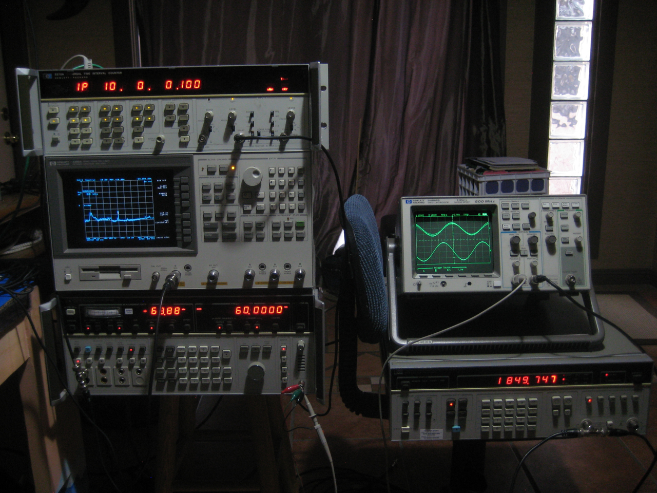
Test setup (click any image for larger)
E-field active antenna drives a 4396A spectrum analyzer and 3586B selective level meter used as a receiver. Audio out of the SLM goes to top channel of scope.
Reference freq of 1848.747 Hz from a 3325A signal generator goes to bottom channel of scope, which serves as a trigger.
There is nothing special about this freq. It's just the tone my particular 3586B produces when set on-frequency.
The entire setup is run open-loop and is dependent on the stability of the internal references of each individual instrument
(and the free-running BFO of the 3586 as others have noted and fixed)
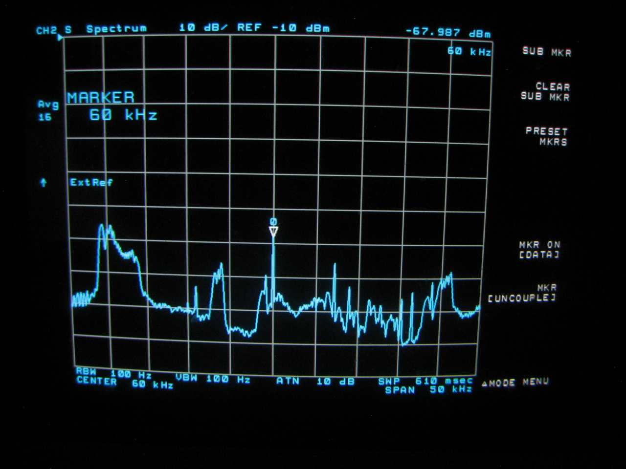
3586B setup for carrier measurement using 20 Hz bandwidth mode and fixed gain range.
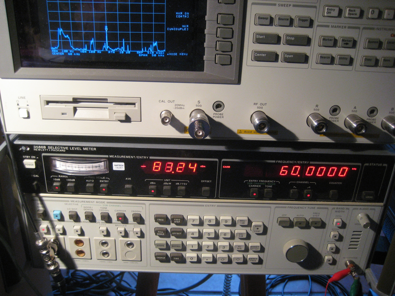
At the time the active antenna was delivering about -68 dBm in a passable S/N environment (all that other junk is noise). My location is about 340 nm from the WWVB site in a large urban city.
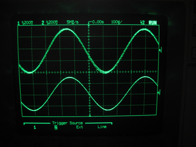
A 1.5 minute, low-res movie (3GPP format) showing the end of the test at 5 PM MST Saturday 3/10/2012. The top trace is the WWVB signal. The bottom is the reference signal. At first you can see the 180 deg phase modulation reversals being applied. At 5pm WWVB goes off-air for a short while. Then the signal returns without the reversals present. Click image to play movie. No audio, but see below.
Added March 11, 2012
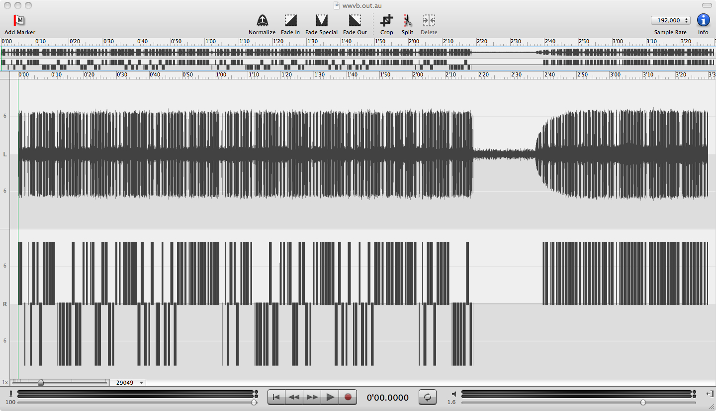
3:30 minutes of post-processed audio from the end of the test at 5 PM. Top channel (audio left) is the WWVB signal directly from the 3586B.
Bottom channel (audio right) is the reference signal, but processed in two ways: It is gated by the amplitude of the WWVB signal.
It is also offset in amplitude by the phase difference between the reference and WWVB signals. In this way it visualizes the phase information
contained in the upper channel. Note the off-air period and return of the usual fixed-phase modulation.
Click images for larger.
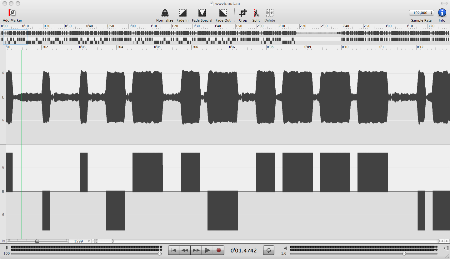
Close up of ten seconds at the beginning of a minute. Note on the left the two frame reference markers sent with opposite phase.
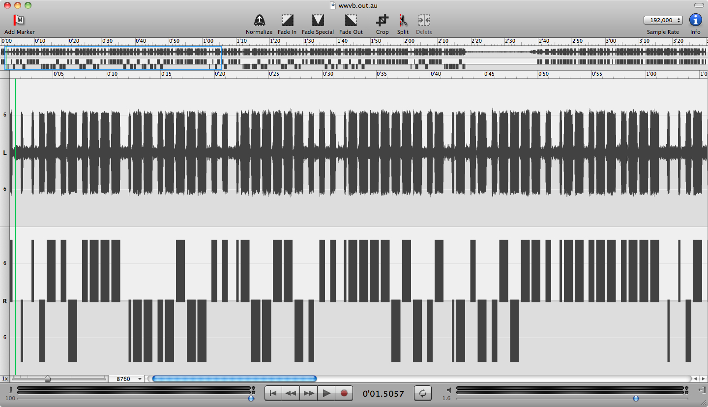
One minute of timecode. For the few minutes I was recording the phase pattern was constant, repeating every minute.
It did not seem to change with the advancing timecode.
ref: WWVB Time Code Format [tf.nist.gov]
Use your favorite waveform viewing & editing program to see this in more detail.
Click images to play audio and/or download file.
Added March 17, 2012
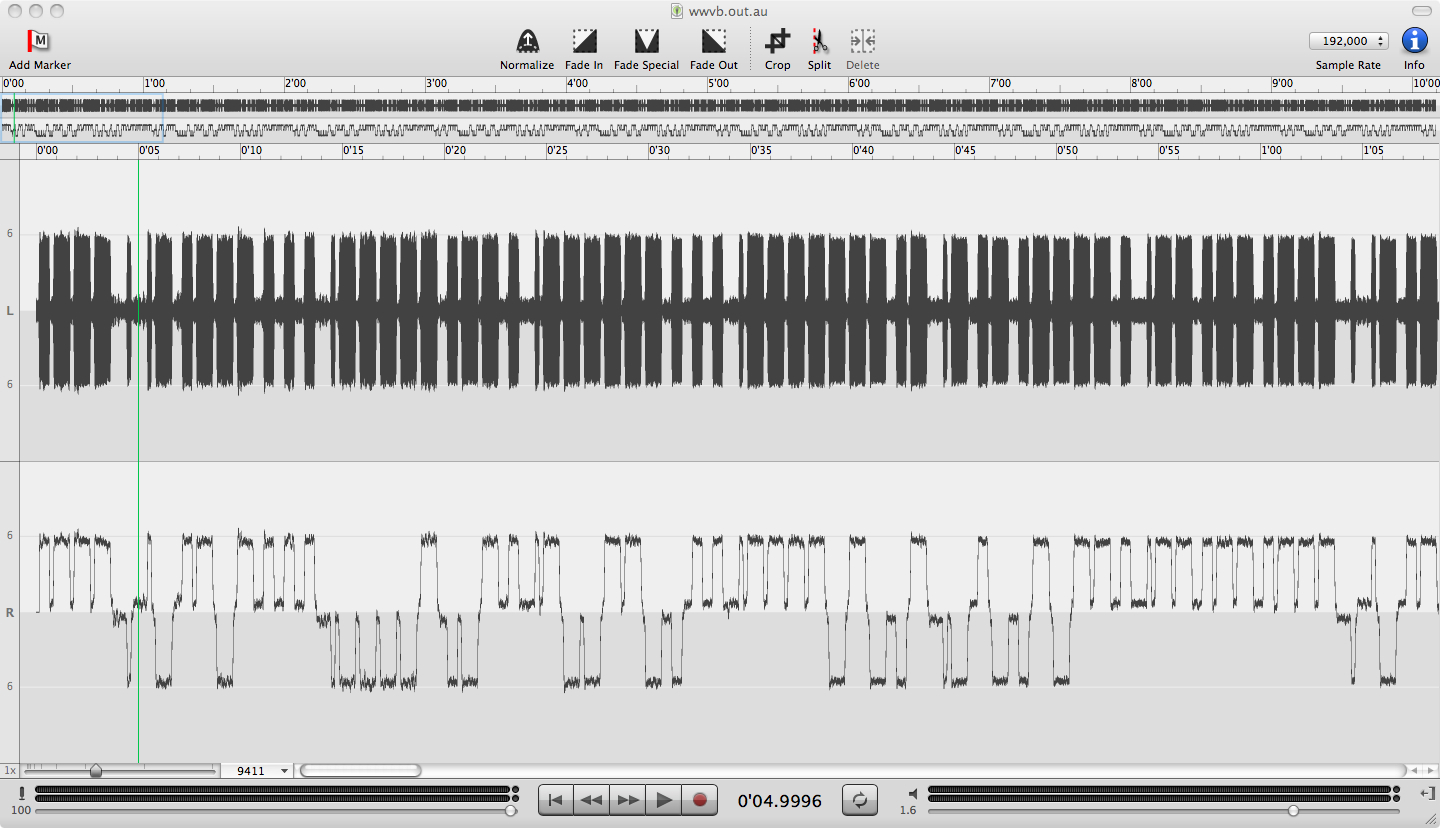
Ten minute long recording made beginning at 2:27 AM MST (9:27 UT) March 10.
As with the 5 PM capture the phase modulation is this constant pattern repeating every minute:
1011011110 0000100111 1001100111 1111010010 0100101111 1111111110
Click images to play audio and/or download file.
Added March 21, 2012
At the request of fellow Time-Nuts member Peter Monta I tried to make some wide-bandwidth recordings of the normal, AM only, WWVB signal.
My previous recordings were all done using the 20 Hz bandwidth setting of the 3586B to limit the effects of local noise.
I first tried connecting the active antenna directly to the input of my 192 ksps sound card. But predictably there was not nearly enough signal,
even at maximum input gain, to make it seem worthwhile (i.e using enough bits of the ADC).
I then looked into what higher bandwidth points might be available inside the 3586:
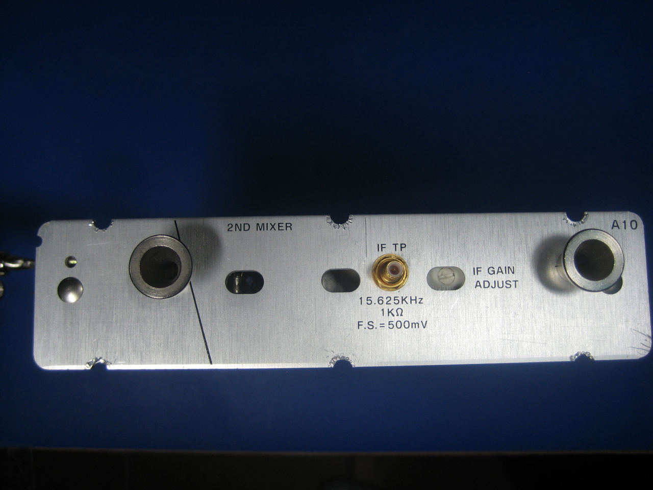
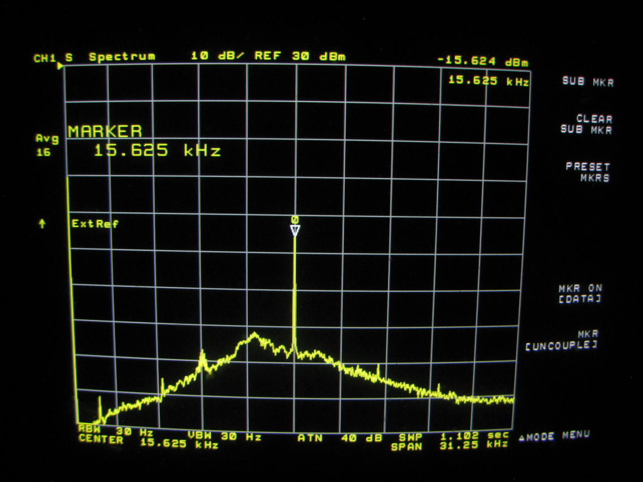
The second mixer module shown here has this nice test connector that couples to some of the 15.625 kHz second IF signal. You can then simply borrow the existing cable that sends the 10 MHz ref signal to the back panel and plug it in here. A very easy way to get the IF signal out of the chassis.
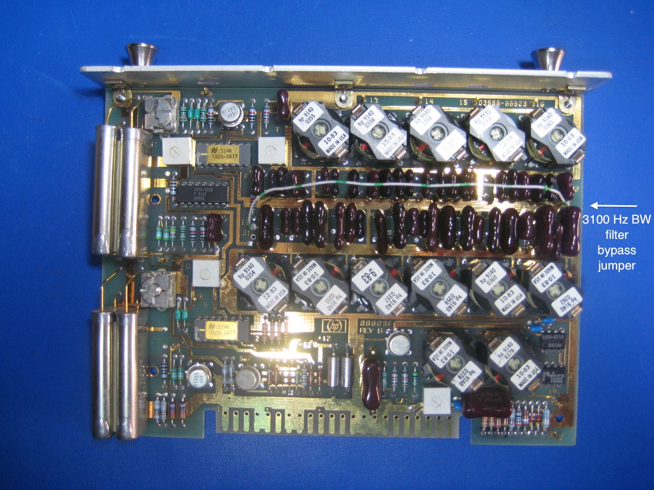
Unfortunately the first IF at 50 MHz has a 10 kHz wide half-lattice crystal filter. So this sets the overall bandwidth of the instrument. Interestingly, a closer look at the schematics shows that HP designed-in some filter bypass jumpers as a service aid. Problem solved:

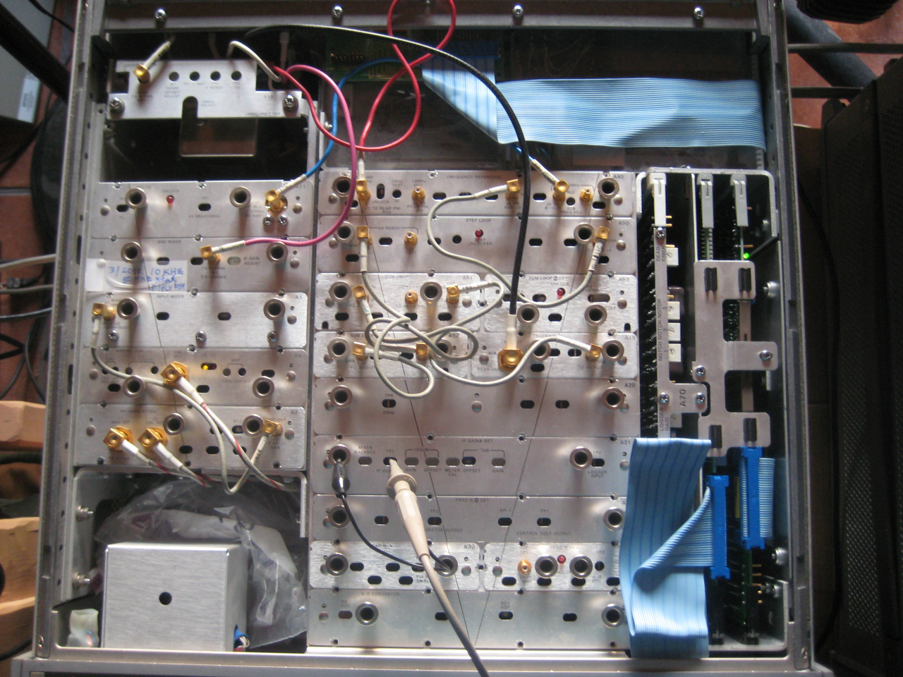
But despite the various amplifiers along the path there is still not enough signal at this point to properly drive the sound card. However, the IF gain & detector module has a test point where you can attach a scope probe through a cutout in the board connector plate (see 4th center module from bottom in the chassis view picture above). This point is just before the product detector, and there is enough gain here (-16 dBm) to drive the sound card input to about 1/3 of full scale. A problem though is that the 3100 Hz bandwidth filter in the preceding IF filter module is always inline. Fortunately, it too has a set of jumpers to remove it from the signal path:
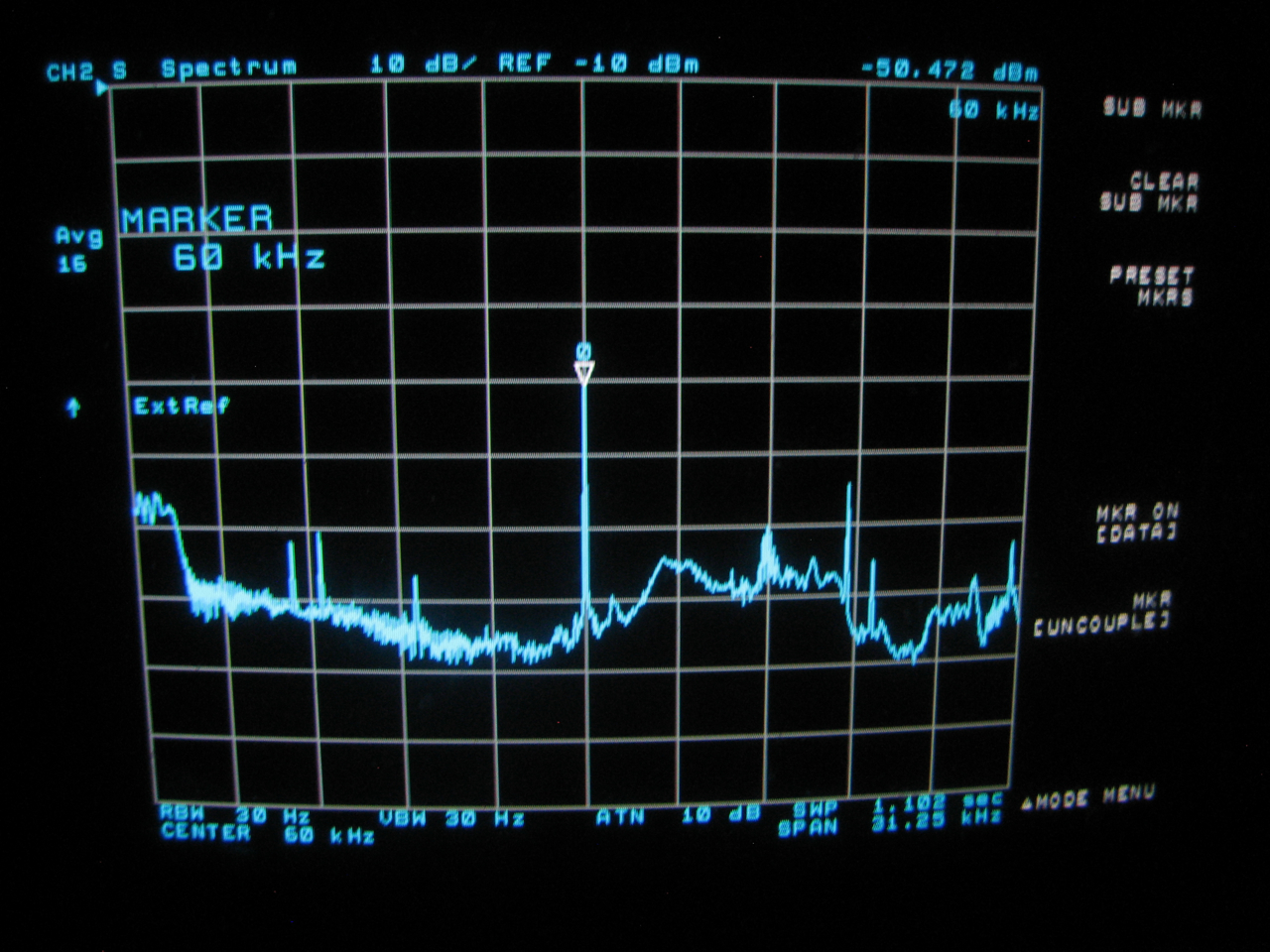
RF signal from active antenna compared to the IF signal from the 3586B. Same freq span, RBW and dB/div. Just different CF and ref point. Note that the frequencies are reversed in the IF, i.e. lower frequencies are to the left. There are obviously some problems with the wide-band gain flatness here.
Five minute long recording made at 44.1 ksps with 24-bit samples (about 40 MB). Remember that WWVB will appear at 15.625 kHz, not 60. Click images to play audio and/or download file.