HP5370 Processor Replacement Project
14-Jun-2018
Important note about the software distribution:
It was discovered several days ago that the 5370 image file for the Beagle is instead an
old KiwiSDR image.
The image file and download script has been fixed. So if you have had
problems please try downloading and re-flashing again. The new sha256 checksum for the correct
image file is:
5025869856d9061a23e27768ca55428dcd1691cd4591d08500ad558f57ae2072
Please see the
project documentation
on github.
Also, we have discovered that the software does not work with the Seeed BeagleBone Green
as we had thought. Please only use an original BeagleBone Black with the board.
5-Jun-2018
Thanks everyone, but we are now sold out of boards. There will not be another production run as we hardly have enough time for our current KiwiSDR project.
29-Mar-2017
The Debian 8 Linux distributions shipped with newer Beagles is incompatible with the 5370 software.
The project documentation
has been updated with a procedure for re-flashing the Beagle with a distribution including working 5370 software.
25-Feb-2016
Boards are available again for shipping. We have about 20 in stock.
Cost is USD $55 for the board only. I'm no longer able
to offer a bundle with the BeagleBone included.
But a BeagleBone Black or Green can be purchased from many sources (either will work with the board).
Shipping from New Zealand to most locations is:
- $14 International airmail, 3-4 weeks, not tracked
- $32 International courier, 1-2 weeks, tracked
- Please include phone number as required by courier
- $5 New Zealand by NZ Post courier
23-Feb-2015
Just a quick update. We still have plenty of boards in stock.
Around October or so
Beagles started appearing in continuous stock at the larger US distributors
(Mouser, DigiKey) in sharp contrast to the supply shortages prior.
And they continued to be in stock for many months until just now in February.
I wonder how much of this was due to the production ramp-up of the Element 14 version?
The
CircuitCo board shipments
seem to have been relatively constant.
17-Oct-2014
Version 3.4 of the software is now available.
When using the "halt" command from the front-panel menu, "halting..." will show on
the instrument display. When Linux has completely halted the display will then be blanked.
At that point it is safe to power off the instrument. This new behavior applies to both the
Angstrom and Debian versions of the software.
Please refer to the Quick Start guide on GitHub, or in the tar distribution file, for software upgrade instructions.
Links to these are in the next entry below.
6-Oct-2014
Boards from the second build are ready to be shipped. Please place your order here:
www.jks.com/php/order.html
If you order the configuration that includes a BeagleBone Black you will receive the latest
"rev C" Beagle with 4 GB of eMMC flash memory and running the Debian Linux distribution.
The quick-start guide and software release is here:
github.com/jks-prv/5370_proc
and also
www.jks.com/5370/5370.tgz
12-Aug-2014
There have been enough requests now to warrant a second board build.
If you have not yet indicated your interest please do so by using the "order" link below
(which is currently setup to take interest information, not actual orders).
The prices are slightly higher for a couple of reasons: The build quantity will be less and
the fixed costs have to be amortized over a smaller number of units. The Beagle has had a
US$10 price increase in an attempt to attract more manufacturing capacity. But along with this
the on-board flash was increased from 2 to 4 GB and Debian Linux was substituted for
Angstrom.
Delivery should be near the end of October. I have to port the software to Debian
and of course there are always issues with any sort of contract manufacturing.
2-Mar-2014
Sold Out!
Last Fall I took a poll at the time-nuts mailing list to gauge interest in the project.
I received responses requesting about 25 boards so I doubled that and had 50 made.
Always a tricky proposition to balance capital outlay versus demand forecast.
The order page is now setup to collect demand information for a future board build.
So if you're interesting in purchasing in the future please use the order page to let me know.
I should be able to get boards built and delivered pretty quickly now that the
supplier is already setup.
www.jks.com/php/order.html
28-Feb-2014
Thanks to everyone who has ordered. Out of the original build of 50 boards I'm now down to
less than 10. The exact numbers remaining are on the order page.
I might actually break even on this project, lol.
Version 3.1 of the software is out on Github and as a tarball:
www.jks.com/5370/5370.tgz
Besides the new menu mode interface and saving of last instrument setup as described below
this version handles powering the instrument on/off while the BBB continues to run if
powered continuously over the USB-mini connection.
There is ongoing discussion about using battery & supercap solutions to provide hold-up power
for an orderly BBB shutdown. Also the concept of running Linux from a primary read-only filesystem
and disposable ramdisk or similar.
24-Feb-2014
I am now accepting general orders for the 5370 board here:
www.jks.com/php/order.html
For an introduction read the Quick Start guide here:
github.com/jks-prv/5370_proc
I've shipped 16 boards so far and everything looks pretty good. Thanks to Chuck Harris
for suggesting a way to halt the Beagle/Linux from the 5370 front panel and helping
me debug it. You can now set the Ethernet IP address via the front panel.
Also the last instrument settings are restored on the next startup
(thanks to John Miles for the suggestion).
The only caveat is that the BeagleBone Black continues to be in short supply. But with
enough patience you can find them.
9-Feb-2014
Orders are now shipping on a small scale to those who expressed an early interest in the project.
It has become somewhat easier to obtain a BBB but the larger distributors still show no stock
as they (presumably) fill backorders.
Many thanks to fellow time-nut and beta tester Orin Eman
for patiently working with me to fix a few bugs. I now know how to use the Programmable Realtime Unit
[PRU] co-processor of the BBB if you happen to need advice on that particular kettle of fish.
The project files on github show how to bundle PRU code with an app together with the PRU tools
(assembler, loader) all glued together with a Makefile into a self-contained distribution.
18-Jan-2014
An updated README.txt file is now on GitHub
github.com/jks-prv/5370_proc
that has complete instructions for installing the 5370 software on the BBB should
that be necessary (e.g. you attached your own BBB to the board). Also more complete
information about connecting to the BBB with a login session over the network and
performing development on the code.
12-Jan-2014
I have received the 50 assembled boards and they work fine. Build quality is excellent.
The problem now is that the BeagleBone Black is very difficult, if not impossible, to find in stock.
CircuitCo shipped 4,400 since January 1 and yet the distributors still show no stock.
They're probably filling backorders. More than 100K have been sold to-date.
The current guess is that BBB is being used inside other products without
proper demand forecasting getting back to CircuitCo. Small-volume purchases by the
community are getting locked out as a result.
Of course I'm contributing to this problem to a small degree.
This situation will eventually get sorted because people purchasing for products can't afford to have
unpredictable delivery.
The Raspberry Pi probably went through the same thing.
Meanwhile, I'm fine tuning the software distribution and writing documentation.
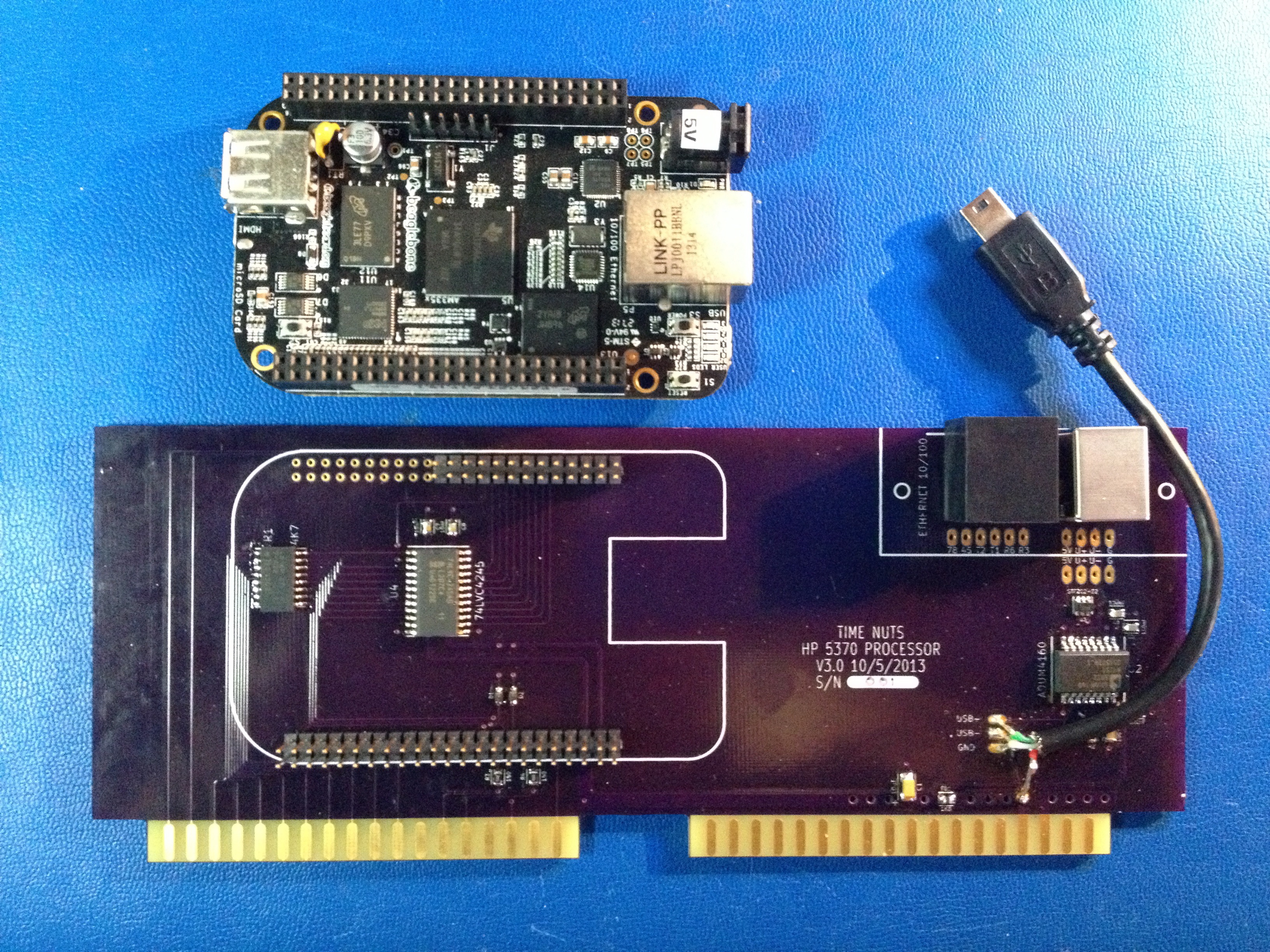
Click images for larger.
12-Nov-2013
An order for 50 assembled boards has been placed with
UPP Technology International Co., Ltd.
after a recommendation by fellow Time-Nuts member Didier Juges.
I am working on building a test fixture for their post-assembly testing.
Estimated delivery is four to five weeks.
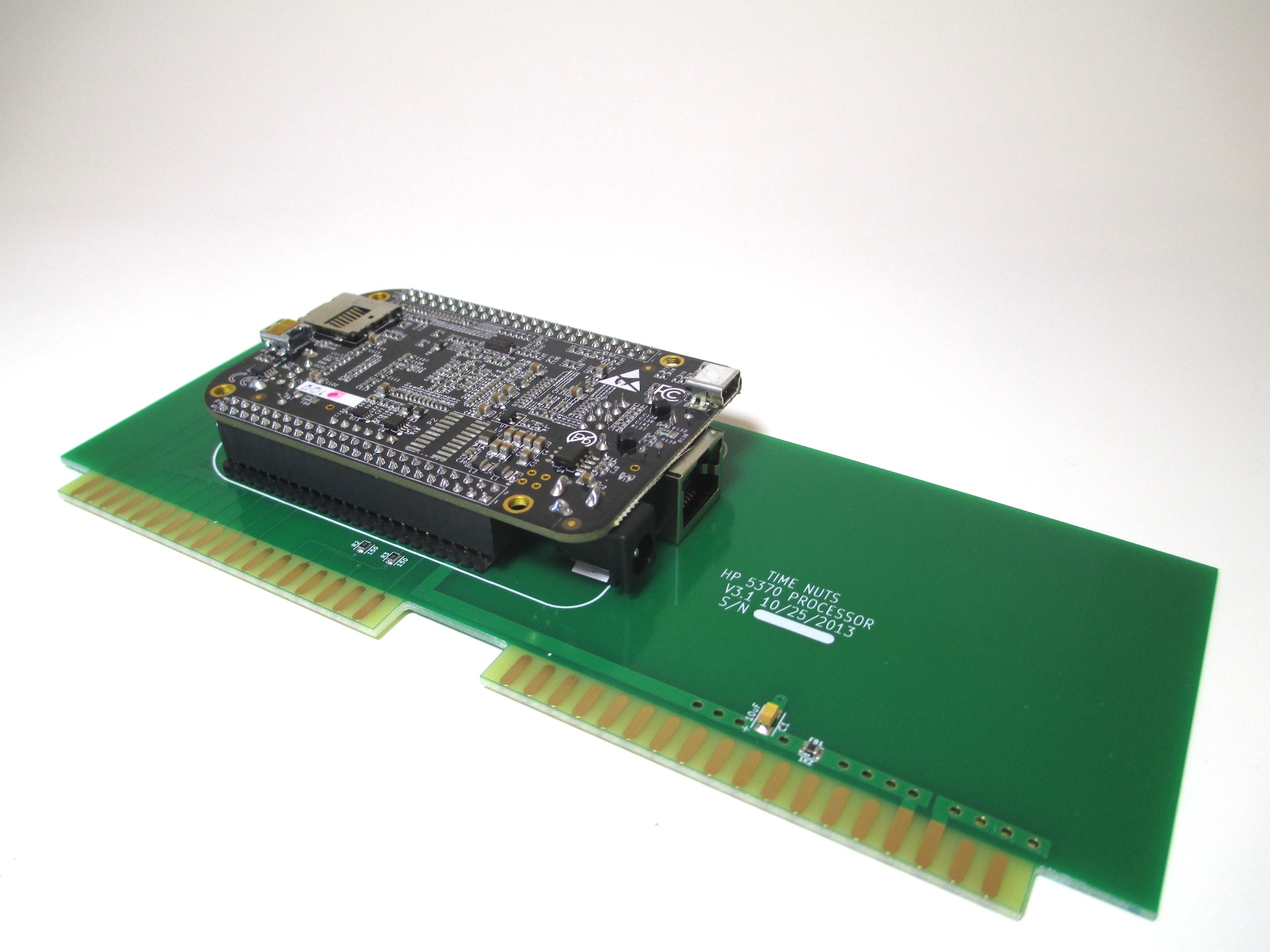
26-Oct-2013
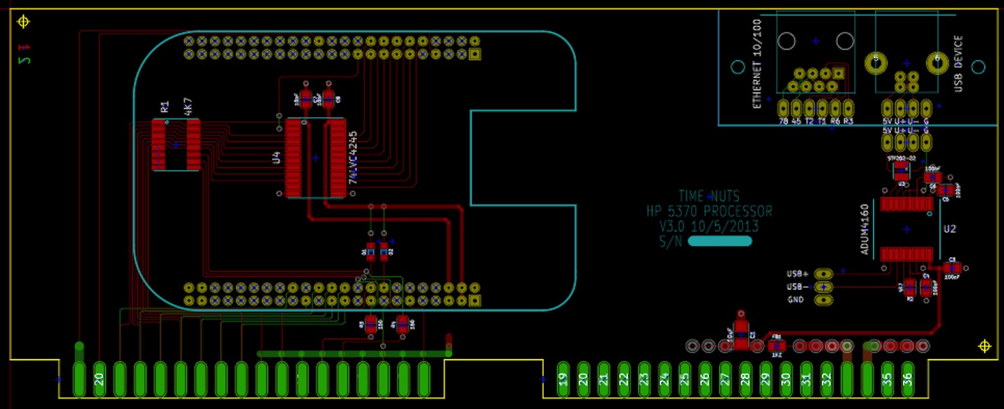
Source code, documentation, Gerbers & drill files, BOM, KiCAD schematic and PCB layout are now on Github:
github.com/jks-prv/5370_proc
I decided to pull the USB isolation stuff off the board since it's pricey and
uncertain when it might be working with the BBB. It can be part of a separate
back-panel connector board in the future. You can still use USB with the BBB,
you just won't have galvanic isolation. You could also run USB-WiFi off of a
USB cable dangling out the back of the instrument I suppose. So for now the
best way is to use a wired Ethernet connection.
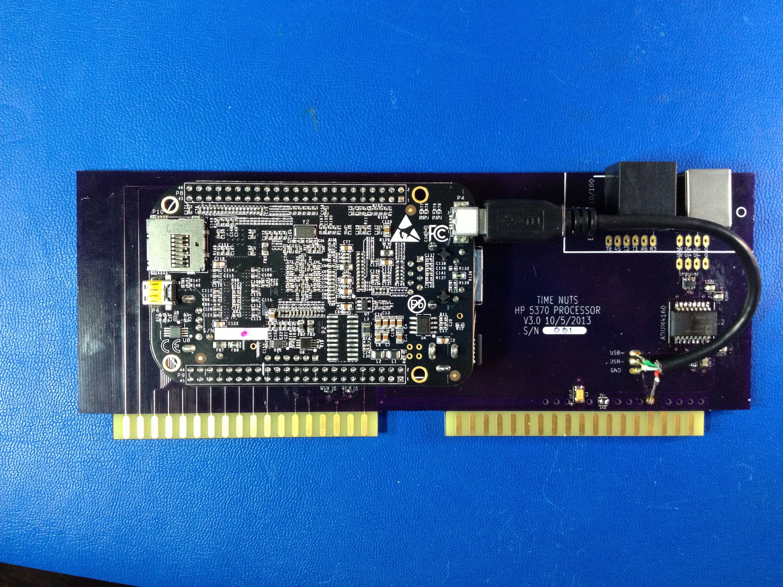
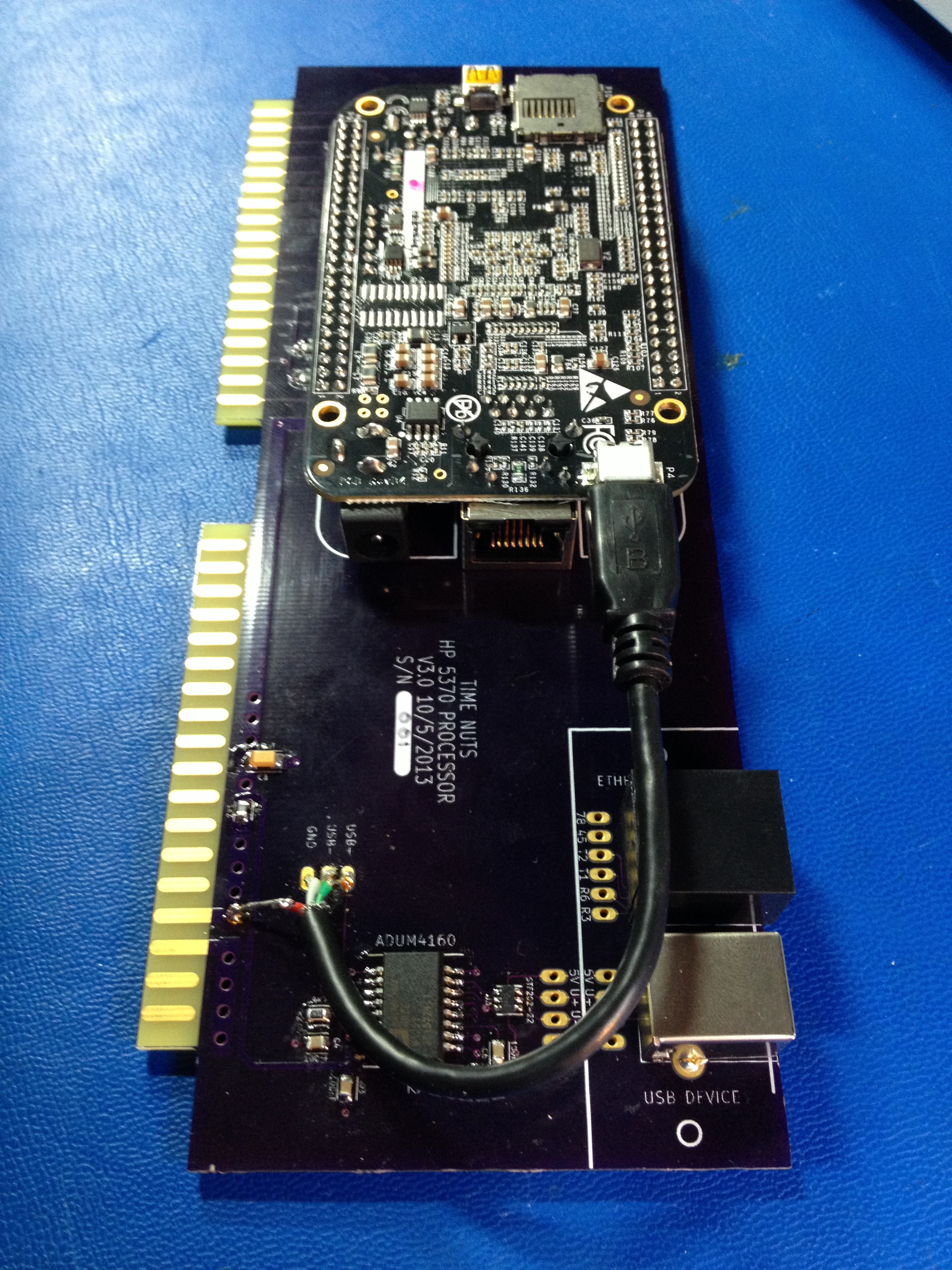
20-Oct-2013
Okay, working. Except for the isolated USB because the BBB host USB port seems to refuse to auto-negotiate down to
the 12 Mbit/s USB 1.x speed. It looks like it's always running at the 480 Mbit/s USB 2.0 speed
(the Analog Devices isolation chip I use can only handle USB 1.x speeds). But Ethernet works fine
as expected.
Click images for larger.
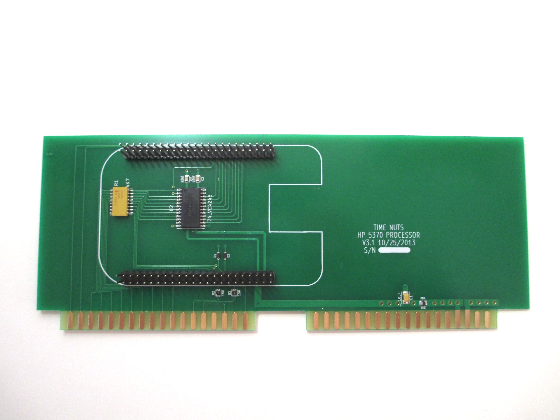
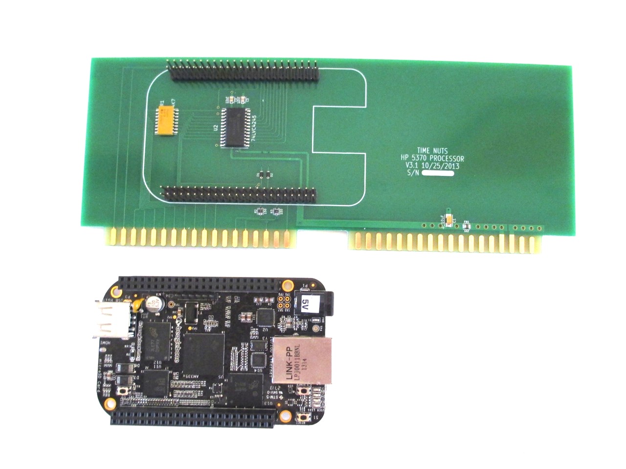
5-Oct-2013
Alright, enough excuses. I sent this board to
OSH Park
this morning:
Click image for larger.
25-Sep-2013
So this project is on hold for a couple of reasons.
The newly available
BeagleBone Black single-board computer at USD$45 is cheaper than the parts cost of
the microcontroller and associated components I was using.
And you end up with a 1 GHz processor instead of 55 MHz, 2GB/512MB of Flash/RAM instead of
512K/128K and it runs Linux instead of a pile of standalone system code (okay, some people would say
that's a step backwards).
The obvious redesign now is a much simpler 5370 board
that a BBB can just plug into. Such a board would need some
5370 backplane bus 3.3 - 5V level shifter/drivers,
the USB isolator circuit and the breakaway PCB section containing the USB and Ethernet connectors
for the 5370 back panel.